Simple & Repeatable
June 21, 2022 | By John Siegenthaler
Delivering comfort and convenience by combining single zone cooling and multi-zone heating using heat pump system designs.
The versatility of modern hydronics technology allows designers to create systems that are “customized” to the needs, and constraints of almost any building. While best known for space heating, most modern residential systems also include provisions for heating domestic water.
Still, for decades, one of the “shortcomings” of smaller hydronic systems has been the inability to cool buildings, undoubtedly swaying many prospective clients to ducted forced air because it provides both heating and cooling.
This long-standing shortcoming is changing as the future of energy supply for heating continues to progress away from fossil fuels and toward electricity.
Heat pumps, in both air-to-water and geothermal water-to-water configurations, are increasingly being used instead of fossil fuel boilers. This transformation brings the ability to provide chilled water cooling, and thus a more complete solution to comfort. That’s a really “big deal” in my opinion.
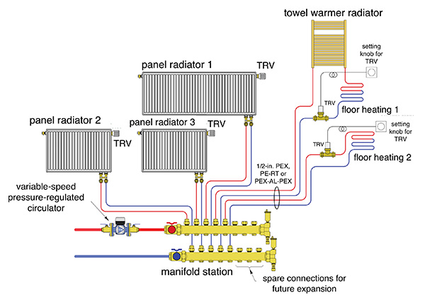
Figure 1. A combination of heat emitters all served by homerun circuits from a common manifold.
A great combination
An approach I like to promote is multiple heating zones in combination with single-zone cooling. The heating distribution system could use one type or a combination of heat emitters.
An example would be radiant floor, wall, or ceiling heating in some areas combined with panel radiators in other areas. Ideally, all heat emitters would be sized for the same supply water temperature. This keeps the system simple by eliminating the need for mixing.
Figure 1 (above) shows a combination of heat emitters, all served by homerun circuits of ½-in. PEX, PE-RT or PEX-AL-PEX tubing from a common manifold station.
Flow to the manifold station is provided by a variable speed pressure-regulated circulator set for constant differential pressure.
Each emitter is equipped with a non-electric thermostatic radiator valve. That valve is built into the panel radiators. The only thing needed to make each panel radiator into an independently controlled zone is to screw a thermostatic operator onto that integrated valve.
The other two circuits show a combination of floor heating and a towel warming radiator. Flow through these circuits is controlled by an external thermostatic valve equipped with a remote adjustment dial typically mounted to a wall.
This combination of thermostatic valves provides five independently controlled heating zones. As the valves open, close, or modulate flow, the variable-speed pressure-regulated circulator senses the “attempt” to change differential pressure and immediately adjusts motor speed to cancel out that attempt. This allows the flow in each homerun circuit to remain stable regardless of what zones are active.
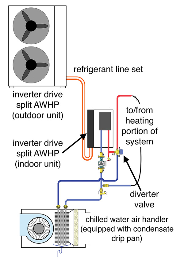
Figure 2. An example of a low-ambient (split system) air-to-water heat pump used for heating (and cooling) energy.
Hot & Cold
In Figure 2 (above), a low ambient (split system) air-to-water heat pump is used as the source of heating (and cooling).
The heat pump is equipped with a variable speed inverter drive compressor, allowing it to modulate both heat output and cooling capacity down to about 40% of peak rating.
The compressor speed changes based on maintaining user-specified leaving water temperatures for heating mode and cooling mode operation. In most systems this allows the heat pump to supply an air handler sized to the building’s cooling load without use of a buffer tank—provided the air handler is not smaller than the minimum cooling capacity of the heat pump, and there is only one zone of cooling.
As a “split system” there is no water in the outdoor unit, and thus no need to protect it from freezing. This eliminates the need for antifreeze, which is required when a monobloc-type air-to-water heat pump is used.
The diverter valve directs flow leaving the heat pump to the heating or cooling portion of the system. It should be configured with its normally-closed port, which is usually designated as “A” supplying the heating portion of the system, leaving the normally open port, which is usually designated as “B,” to supply the cooling mode.
The “A” port should only open when the heat pump is operating. This allows the diverter valve to prevent reverse thermosiphoning through what could otherwise be an unblocked piping path between the upper and lower portions of the tank.
It also eliminates the need for a check valve to otherwise prevent reverse thermosiphoning.
The air handler supplies a ducted distribution system. Since this portion of the system is for cooling, the ideal arrangement would put the outlet registers in the ceiling or high on the walls. This allows the cooled air to mix with room air without creating drafts.
In cold climates it’s best to install the air handler in conditioned space. This all but eliminates the possibility of freezing water in the air handler’s coil during winter. It also reduces the potential for energy-wasting convective air flow through the air handler and ducting due to temperature stratification in the building.
If the air handler has to be mounted in unconditioned space some means of freeze protection is required. The possibilities include draining the coil during winter, using anti-freeze in the system, building an insulated enclosure around the air handler, or installing heat tracing cable and hoping that no long duration power outages occur. I’m not a fan of any of these if they can be avoided.
Even small air handlers can generate several gallons of condensate when operating in cooling mode on a humid day. Be sure to pipe up a condensate drain.
Depending on applicable codes, this drain might be connected to the buildings DWV system, or it may have to be routed to a separate interior or exterior drainage point.
When the air handler is installed above finished ceiling I recommend installing it over a secondary drain pan that would capture leaks from the air handler’s internal drip pan and route them to a suitable drain.
Thermal Flywheel
The final subsystem is a reverse indirect tank that provides buffering for the space heating zones, which typically have heat transfer requirements much smaller than the minimum heating capacity of the heat pump. The concept is shown in Figure 3.
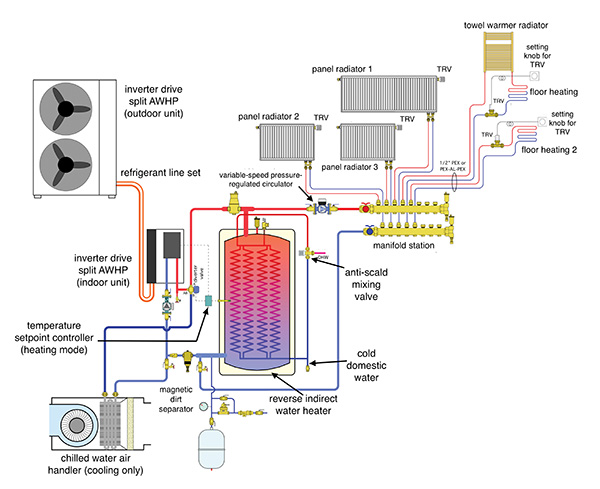
Figure 3. A complete system including an indirect water heater.
The tank piping is configured around one currently available reverse indirect.
It’s a “two-pipe” configuration, which allows for “direct-to-load” heat transfer at times when the heat pump is running at the same time as space heating load.
The Brains
During heating mode operation the temperature of the buffer tank is monitored by a setpoint controller. When the sensor at the midpoint of the tank drops to some minimum value the heat pump is turned on. This happens regardless of any demand for space heating.
The goal is to keep the water in the tank’s shell warm enough to provide domestic water heating (or preheating) whenever there’s a draw at a fixture.
Once turned on, the heat pump continues to operate until the tank sensor reaches some upper limit. That limit should be several degrees lower than the safety high limit setting programmed into the heat pump’s internal controller.
This is where a tradeoff needs to be made. The lower the temperature at which the buffer tank is maintained, the higher the heat pump’s coefficient of performance. However, for tank temperatures below about 115F, the domestic hot water (DHW) will only be “preheated” rather than fully heated. Preheated domestic water requires a temperature boost prior to use at fixtures, and that boost could come from a single electric on-demand tankless heater. It could also come from multiple smaller-capacity electric tankless heaters located close to each fixture.
It’s also possible to base the buffer tank temperature on outdoor reset (rather than setpoint) . The warmer it is outside the lower the buffer tank temp.
This keeps the water in the tank just hot enough to provide the building’s current heating load. Still the lower the tank temperature, the greater the required boost in DHW leaving the tank.
The “optimal” temperature control for the tank must factor in the energy used for space heating and DHW, the COP of the heat pump operating over a range of both water and outdoor temperatures, and the cost of electricity used for direct resistance heating.
Based on simulations I’ve done there appears to be a slight advantage to controlling the tank based on outdoor reset, versus maintaining the temperature high enough to provide DHW.
During cooling mode the heat pump monitors its leaving water temperature, and adjusts compressor speed to maintain a suitable setpoint, typically in the range of 45F to 50F.
DHW First
To ensure DHW availability the system’s controls give priority to maintaining the temperature in the tank. When required the heat pump switches from chilled water to heating mode. The time to boost the tank during warm weather should be minimal because the system is operating at high heating capacity.
When the tank reaches is upper temperature setting the heat pump switches back to cooling.
At that time the heat pump and nearby piping contain hot water. It typically takes about three minutes for the heat pump to restart in cooling mode. It may take another two to three minutes to chill down the water in the heat pump and surrounding pipe. During this time the system controls should keep the blower in the air handler off to prevent a short burst of warm air from the ducting system.
It’s in your future
The ability of heat pumps to provide cooling through a central air handler—combined with heating by individually controlled panel radiators—is a simple and repeatable concept that’s ideal for modern homes, especially those aspiring to net zero status.